


Understanding Ripple Current to Properly Manage Heat in Power Capacitor Design
Ripple current generates heat inside capacitors, making proper capacitor selection, derating, and thermal management essential for long-term reliability in power electronics.
In power electronics, voltage is rarely perfectly DC. Switch-mode power supplies, inverters, and converters all generate AC ripple that flows into and out of capacitors. While a ripple current rating may seem secondary to a capacitance or voltage rating, in real-world designs, it is often a limiting factor for long-term reliability. This is because ripple current generates internal heat, and excessive heat is a primary driver of capacitor failure. To prevent premature failure, it’s critical for engineers selecting power electronics capacitors to truly understand ripple current ratings.
How Ripple Current Causes Self-Heating
Ripple current is the AC component of current superimposed on a DC bias. Since every capacitor has some inherent equivalent series resistance (ESR), when ripple current flows through that resistance, it dissipates power as heat inside the component. The amount of heat generated can be calculated using the following formula:
P = I²rms × ESR
P = Power dissipated (watts)
Irms = RMS current flowing through the component (amps)
ESR = Equivalent Series Resistance (ohms)
That power translates into a temperature rise inside the component that can be calculated as follows:
ΔT = P × Rth
ΔT = Temperature rise above ambient (°C)
P = Power dissipated as heat inside the capacitor (watts)
Rth = Thermal resistance from the capacitor’s core to ambient (°C/W)
This is important to understand because as core temperature increases, component lifetime decreases, often dramatically. A common rule of thumb derived from Arrhenius modeling is that lifetime halves for every 10°C rise above rated temperature. Therefore, a capacitor designed for 5,000 hours at rated conditions can quickly become a 1,250-hour part if thermal stress is not properly managed.
Temperature rise does not affect all capacitor technologies equally though. Instead, it accelerates different failure mechanisms depending on construction and materials:
- Aluminum electrolytics: Electrolyte evaporation triggered by vapor pressure
- Multilayer ceramic capacitors (MLCCs): Moisture ingress and cracking in ceramics from differential thermal expansion
- Polymer capacitors: Oxidation
- Film capacitors: Generally robust, but still subject to thermal stress limits
What the Datasheet Really Tells You About Ripple Current
Ripple current ratings are always specified under defined conditions: frequency, ambient temperature, and allowable temperature rise. For example:
- Aluminum electrolytics are often rated at 120 Hz
- Polymer capacitors are commonly rated at 100 kHz
- MLCCs typically allow higher temperature rise (10–20°C) than electrolytics (often 5°C)
While the datasheet provides ripple current specifications, interpreting them correctly, especially across different capacitor technologies, requires careful attention to test conditions and frequency dependence. For starters, engineers must evaluate ripple at the actual switching frequency of the application, not just the reference frequency on the datasheet. Plus, ESR varies with frequency, and manufacturers provide correction factors to account for this.
Key parameters to review when thinking about ripple current include:
- RMS ripple current (Irms)
- ESR at operating frequency
- Thermal resistance (Rth)
- Frequency correction multipliers
- Temperature derating curves
Without making the adjustments mentioned above, comparisons across capacitor types can be misleading.
Choosing the Right Technology for Ripple Performance
Ripple current capability is fundamentally tied to capacitor construction and materials. Because ESR, thermal resistance, and frequency behavior vary significantly by technology, selecting the right type of capacitor is critical. Different capacitor technologies excel in different parts of the frequency spectrum:
- MLCCs: Extremely low ESR and outstanding performance above ~100 kHz. Ideal for high-frequency decoupling and output filtering, though designers must account for DC bias capacitance loss.
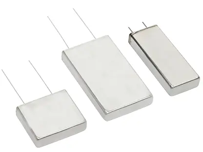
- Film capacitors: High ripple density and long operational life. Excellent for higher voltages and lower-to-mid frequency ripple.
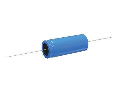
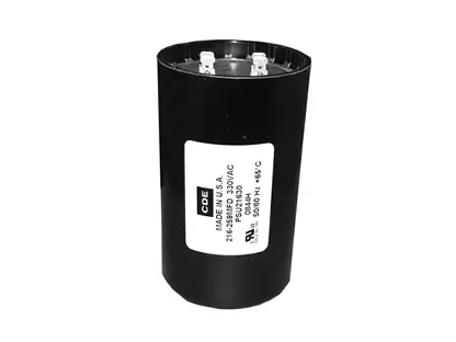
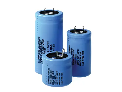
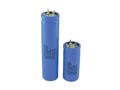
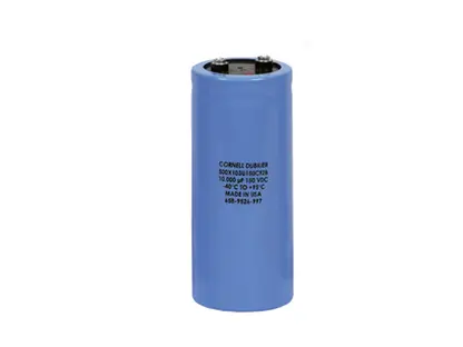
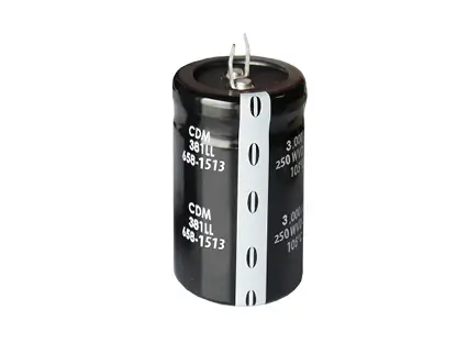
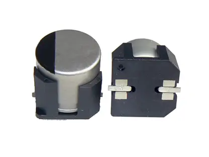
- Aluminum electrolytics: Offer the highest capacitance per cost. Best suited for bulk energy storage and 50/60 Hz rectification.
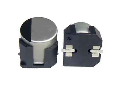
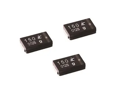
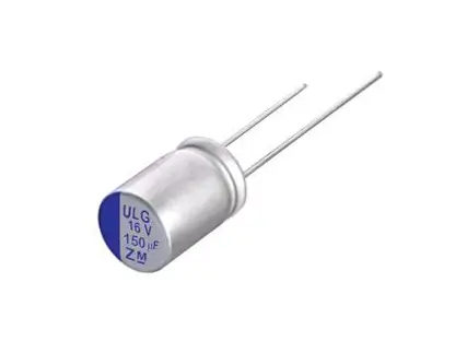
- Aluminum polymer: Lower ESR than traditional electrolytics and strong ripple handling in compact footprints, bridging the gap between MLCCs and electrolytics.
The optimal solution often combines technologies to manage ripple across the full frequency range.
Practical Strategies to Reduce Ripple-Related Risk
Ripple current ratings should never be treated as absolute operating targets. Designing to the edge of the datasheet limit leaves little room for real-world variation in temperature, airflow, or switching frequency. Below are three practical strategies to consider to help reduce ripple-related risk:
- Derating: Derate ripple current to 50 to 70 percent of the datasheet maximum.
- Paralleling: Parallel identical capacitors to divide current and reduce effective ESR, but avoid mixing values as this can cause unequal current sharing.
- Thermal management: PCB copper planes, thermal vias (0.3–0.5 mm, spaced 0.8–1.5 mm), and enlarged pads reduce Rth by 50 to 70 percent. Note that hybrid networks (bulk + mid-frequency + high-frequency capacitors) can be used to optimize across the frequency spectrum.
A Portfolio Built for the Full Ripple Spectrum
Effectively managing ripple current starts with matching the right capacitor technology to the application’s electrical and thermal demands. With both MLCC solutions and Knowles' Cornell Dubilier brand film and aluminum capacitors, Knowles offers a uniquely broad portfolio for this. That means engineers can evaluate ripple performance across technologies and select the best-fit solution for long-term reliability.
When ripple current matters, and in power electronics, it always does, technology breadth makes the difference between meeting specifications and ensuring long-term reliability.
Learn more about the impact of ripple current on aluminum and film capacitors or discover how heat rise can impact MLCCs.